Introduction
Interlocked intramedullary (IM) nail, common in trauma and orthopedics, in terms of bones physiology have serious disadvantages. Nail blocks intraosseous blood supply, splints power loads on the limb when walking. Moreover, resorptive diastasis forms between the bone fragments that leads to the slowing of the bone formation. Postoperative complications such as non-union of the bone fragments, delayed union, implant (nail and screws) or the bone fracture still present.
Fracture stabilization is achieved with the help of screws which are installed through the bone at the nail ends. Locking screws add torsional stiffness and pull bone fragments together to achieve stability of the bone-implant system. There is a problem of rotational forces on the locking screws. Such bone-implant system is static and a surgeon can't control reparative processes in these conditions without repeated surgical interventions which have to be made to dynamize bone fixing system. So the IM locking (without screws) of nails theoretically is more preferable. Moreover, the presence of the holes and screws in the nail design introduces the possibility of the implant and screw breakage [1, 2]. Researchers focus on high stress values that occur on locking screws and IM nail [3]. The influence of the distance from the distal locking screw to the fracture on the effective stress (ES) in the screws was investigated [4]. Two situations were analyzed: with and without contact between nail and cortical bone. Stresses in screw were higher without contact than with contact between nail and cortical bone.
It is evident that the design of the standard nail with locking screws itself generates stress concentrations. Therefore, researchers try to introduce new models of IM nails which can be fixed in the medullar canal without locking screws or with the help of proximal screws only.
Ingrassia and coauthors [5] numerically investigated the new IM nail with expanding lower end. Modeling showed good stability of the bone-nail system in case of axial and torsional loading. ES values on screws and nail were between 130 and 280 MPa. Thus, according to the authors, the new implant in addition to a simplified installation procedure provides better stability of bone fragments than standard nails.
Kajzer et al presented [6] the new IM nail with distal expandable end and investigated numerically the nail-femur system under axial and torsional loading at different healing states. Results showed the risk of bone tissue damage at fragment junction and at contact zone between the distal end of the nail and inner surface of the femur. Further studies are needed to investigate the stability loss of the distal end of the new IM nail.
Thus the problem of the new IM nail development is relevant. Such a nail shouldn't have disadvantages of today implants. Design of the new nail should be adequate to the bone morphology and architectonics of medullar canal and should provide good stability of the bone fragments. Such a nail should allow the bone fragments to interact with each other at the fracture area and provide necessary compression at their junction.
At preclinical stage this problem can be solved with the help of biomechanics. The purpose is to calculate stress-strain state of the bone-implant system and to predict the behavior of such a system after surgery under different loading conditions. It is important not only to develop shape and design of the nail, but also to test it in the conditions close to real. Therefore it is necessary to restore a realistic geometry of the bone, to select appropriate forces acting the bone-implant system and to apply adequate constraints.
This work is dedicated to the engineering design of the new IM nail which is protected by Russian patent № 115646. The paper presents analysis of the bone-implant system stress-strain state under the influence of various stationary loads (axial, lateral forces and torsional moment). Loads were applied to the head of the bone. Two types of IM nails (standard lockable (ChM Ltd., Poland) and new developed) were investigated.
Three-dimensional (3D) model of the femur was built using computer tomography (CT) data of the real patient. 3D models of the bone-implant systems were imported into Ansys 14.0 for the finite element analysis. Calculations revealed mechanical characteristics and advantages of the new nail which were compared with standard implant.
Material and Methods
New nail is presented on Figure 1 in two projections. It has a general form of a “rocket” and an internal canal for the elastic blocking element in one of the femur condyles. Its geometry has three edges that are adapted to the anatomy of the femur proximal part. These features eliminate rotational mobility of the bone fragments. Contact area between nail and bone tissue increases significantly. Distal part of the nail has 2 holes. One for distal cortical screw and the other oval hole is associated with internal canal. The oval hole is made for the flexible spoke which should be fixed inside the femoral condyle.

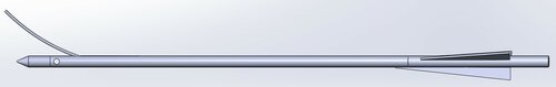
Figure 1. Two projections of the new nail
Human femur realistic 3D model (Figure 2a) was created on the basis of CT images with the help of SolidWorks 2008 software (Dassault Systems SolidWorks Corp). CT scans were collected in Saratov Scientific Research Institute of Traumatology and Orthopedics. It was revealed that optimal periodicity of CT images should be 2-5 mm. In areas with slight changes of bone geometry frequency of CT images should be at least 5-10 mm. It was noted that large number of CT images allowed taking into account particular qualities of the bone structure. On the contrary, a smaller number of images give smooth surface of the bone, but in this case it is impossible to take into account all parameters of the femur geometry. SolidWorks was also used to model a transverse fracture 32-A3.2 [7].
3D femur models were used for the bone morphological characteristics measuring. In proximal part of the femur a peculiar internal metaphyseal architectonics was found. Size of the medullary cavity changed from 54.0±1.6 mm in the neck region of the femur to 31.0±1.3 mm in the middle of the lesser trochanter. Depiction of the femur cortical layer inner surface at the level of lesser trochanter is shown on Figure 2b. It was found that the Adams arc of the femoral neck is strengthened by the bone structure in the inner thigh in the area of lesser trochanter. Its length is about 18 mm. Transverse sizes of this structure are about 8-10 mm.
Figure 3 shows self-stabilization of the developed nail in proximal part of the femur.
a 
b 
Figure 2. a) Shape and size of the femur inner cross sections at the trochanteric zone (sizes are in mm); b) CT cross-sections and 3D model of the femur

Figure 3. New nail self-stabilization in proximal part of the femur
3D static problems of the elasticity theory with contact interaction between bone fragments, IM nail and screws were solved numerically in commercial software Ansys Workbench 14.0 (Ansys Inc., Canonsburg, PA, USA) with the help of finite element method.
To determine optimal size of the mesh elements (to achieve mesh which has no effect on numerical results) mesh convergence problem was solved. It was found that size of the mesh elements should not be more than 0.5 mm. Because of the complexity of geometric models tetrahedral computational mesh consisting of 10-node non-linear finite elements (SOLID187 with translations in the nodal X, Y, and Z directions in each node) was used. SOLID187 has a quadratic displacement behavior and is well suited to modeling irregular meshes. Large deformations (geometric nonlinearity) of the bone, nail and screws were taken into account. The number of nodes for femur, nail and screws was about 1,000,000 for each model of the bone-nail system.
Frictionless contact type was assumed between bone tissue, nail and screw structures. The same type of contact was assumed for the fracture surfaces to account for sliding, separation and force transmission between fracture fragments. The screw threads were not modeled and bonded contact type was assumed between screws and bone tissue [8]. Contact types are shown in Table 1.
Material of the bone fragments was supposed to be homogeneous, perfectly elastic, isotropic with Young's modulus of 1.8*109 Pa and a Poisson's ratio of 0.33. Nail material was also perfectly elastic isotropic (stainless steel with Young's modulus of 1.95*1011 Pa and a Poisson's ratio of 0.33). Distal end of the bone was fixed. Three types of loading conditions were investigated. Axial, lateral forces and torsional moment were applied to the femur head. Types and values of the studied loading conditions are shown in Table 2.
Table 1. Contact types
|
Contact |
Type |
Description |
|
Bone-Nail Nail-Screw Bone-Bone |
Frictionless |
Contact surfaces are allowed to slide freely and contact can open and close depending on the loading. |
|
Bone-Screw |
Bonded |
Both surfaces are bonded like glue. They are not allowed to separate. Not allowed to Slide. |
Table 2. Load values and types
|
|
Loading type |
Value |
|
1 |
Axial force |
600 N, 800 N, 1000 N |
|
2 |
Lateral force |
100 N |
|
3 |
Torsional moment |
10 Nm |
Results
Aim of the numerical simulation in this study was to calculate and compare stress-strain state of the bone-implant systems for different implant and loading types. Results for the standard ChM nail will be presented further. Figure 4 shows ES distribution in ChM nail and screws in case of 600 N axial force. Highest values were achieved at fracture area and at contact area between nail and one of the lower screws. Similar stress distribution was observed for 800 N (Figure 4b – ES on proximal screws, max value is 380 MPa) and 1000 N axial forces (highest values of the ES were about 420 MPa). The highest ES values in case of lateral load were localized at contact area between nail and one of the lower screws. ES reached values of 380 MPa. In case of loading with 10 Nm torsional moment maximal stresses were also concentrated at the lower screw and reached critical values (550 MPa).
a 
b 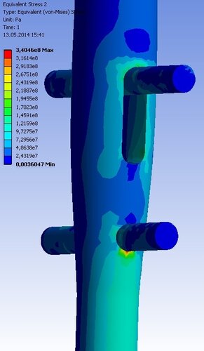
Figure 4. a) ES distribution in the standard nail under 600 N axial loading; b) ES distribution in the proximal part of the standard nail under 800 N axial loading
Next, we present results for the new nail. Figure 5 shows ES distribution in the femur–new nail system under 1000 N axial loading (upper bone fragment is hidden). Figure 5 shows that under axial load the highest ES values occurred in the nail body. Figure 5 also demonstrates that the lower locking screw is less loaded than in the case of ChM nail. Therefore its deformation and possible damage are considerably reduced.

Figure 5. Distribution of the ES in the new IM nail under axial 1000 N loading.
For the lateral force the highest ES values were concentrated on the nail itself at the bone fracture area and on its blades (Figure 6). Locking screw was also practically unloaded. ES values were not critical for the nail material (max value were not more than 140 MPa).
In case of 10 Nm torsional moment, we have got stress distribution showed on Figure 7. ES values were not higher than 300 MPa.
Comparative data on the highest ES obtained for investigated nails is presented in Table 3.
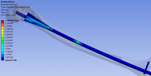
Figure 6. Distribution of the ES in the new IM nail under lateral 100 N loading

Figure 7. Distribution of the ES in the new IM nail under torsional 10 Nm loading
Comparative data of the maximal displacements of the bone head for standard and new nails are shown in table 4. Under axial load displacement of the bone head for standard ChM nail (displacement is 1.11 mm) is smaller than for the new nail (displacement is 1.43 mm) installation. For lateral and torsional loads situation changed. Both of the nails showed similar stiffness under lateral loading. In case of 10 Nm torsional moment the new nail (displacement is 0.62 mm) was twice more stable than standard ChM nail (displacement is 1.20 mm).
Table 3. The highest ES observed in IM nails
|
№ |
Type and value of load |
ES, MPa |
|
|
ChM nail |
New nail |
||
|
1 |
Axial 600 N |
220 |
200 |
|
2 |
Axial 800 N |
340 |
250 |
|
3 |
Axial 1000 N |
420 |
350 |
|
4 |
Lateral 100 N |
380 |
140 |
|
5 |
Torsional 10 Nm |
550 |
300 |
Table 4. Maximal displacements of the bone head
|
№ |
Type and value of load |
Maximal displacements of the bone head, mm |
|
|
New nail |
ChM nail |
||
|
1 |
Axial 600 N |
1.31 |
1.11 |
|
2 |
Axial 800 N |
1.55 |
1.26 |
|
3 |
Axial 1000 N |
1.97 |
1.65 |
|
4 |
Lateral 100 N |
2.95 |
3.36 |
|
5 |
Torsional 10 Nm |
0.62 |
1.20 |
Discussion
Despite the fact that lockable IM nails provide high stability of long bone fractures [9], they have serious disadvantages. Primarily, non-union of the bone fragments usually happen due to breakage of the distal screws and/or distal part of the nail. Therefore, the actual problem now is to improve characteristics of the standard nail or to develop design of the new implant which would take into account disadvantages of standard IM nails. This problem should be solved at preclinical stage with the help of biomechanics and computer modeling methods. Improving the mechanical performance of the IM nail properties could avoid its breakage and resulting clinical complications. Usually researchers use the finite element method for the analysis of the IM nails mechanical characteristics [5, 6, 8]. This is a valuable tool to analyze the stress and strain in the bone-implant system and obtain advantages and disadvantages of IM implants. To perform a biomechanical analysis of the bone-nail system one need to know a lot of mechanical and geometric parameters. These include the precise geometry of the bone and implants, adequate loading and strain conditions, properties of the materials.
While constructing 3D models of bones researchers pay attention to bone morphology and structure of the femoral head. Little attention is paid to the architectonics of the medullary canal which, in our opinion, is playing an important role in studying stress-strain state of the bone-implant system under loading conditions. It is important to take into account morphology of the contact surface, value of the gap [10] and the contact interaction between bone fragments, implant and screws. Often 3D bone models are simplified and smoothed. Nevertheless, in a number of papers authors leave 3D bone models in original form which were obtained from CT data [11, 12]. Such geometry is suitable for numerical calculations, however, the boundary conditions (BC) statement; meshing and other operations are more complicated. So in this study it was decided to construct realistic bone geometry on the basis of CT data, but for the convenience of the numerical simulation and BC statement smooth curves were used to approximate bone cross-sections. So it was possible to construct a smooth and realistic geometry of the femur. The construction of the femur bone 3D model was divided into two stages. At the first step the CT data was used and isolated cross-sections of the femur were created. Then slices were imported into SolidWorks system [8] where they were outlined manually using splines. Thus obtained closed loops were then connected into the smooth volume (Figure 2b).
Many scientists study the mechanical parameters of cortical and trabecular bone tissues. Trabecular bone has significantly anisotropic structure. A number of studies showed that in terms of mechanical properties it can be considered as isotropic [13-15]. To simplify the formulation of the problem we assumed that cortical and trabecular bone tissues were isotropic. A comparison of finite element analysis, synthetic femurs and human cadaveric femurs suggests that isotropy and linearity is a fairly good approximation of the femur bone tissue behavior [16-18]. Range of the bone tissue elastic moduli variation is large enough [19]. This is due to differences in research methods, methods of sample preparation etc. Most researchers conclude that the elastic modulus of trabecular bone is 20-30% lower than the elastic modulus of cortical bone [20-22]. Nevertheless, several authors argued that elastic modules of the cortical and trabecular bone tissues are identical or differ insignificantly [23, 24]. In this work to simplify the construction of the bone geometry, problem statement and its solution we considered homogeneous bone. Cortical and trabecular tissues had identical mechanical properties. We used the empirical formula [25] to obtain mechanical properties of the studied femur on the basis of CT data.
Researchers often investigate axial, lateral and torsional loading of the bone-nail systems [26]. Lower end of the bone is usually constrained [18, 27]. Values of axial forces vary from 450 to 1000 N [18]. The value of torsional moment as a rule is about of 10 Nm [28, 29].
Now we will discuss numerical results for the standard and new nails.
Axial stiffness of the bone-implant system for the new nail was between 500 and 521 N/mm and for the standard nail – between 632 and 637 N/mm. Stiffness of the bone-implant system for the standard nail was 26% higher compared with the same stiffness for the new nail. Nevertheless, the new nail provides required stability of the fracture under investigated axial loads. In case of lateral force the new nail provides a greater stiffness than the standard nail. Displacement of the femoral head for the new nail was 2.95 mm and 3.36 mm for the standard nail. So the new nail showed lower axial stiffness than the standard, indicating that the proximal fragment in this case is more mobile in the axial direction. This confirms that the dynamization procedure is not required for the new nail.
In the case of torsional moment max displacement of the femur head for the new nail was 0.62 mm and for the standard nail – 1.20 mm. These data suggest that the new nail provides higher (practically twice) stability under torsional loads than the standard nail.
Numerical results for the standard ChM nail showed that in all three cases of loading ES reached the highest value at the lower screws that hold the nail. This can be explained by the fact that under such loading and method of fixing, the greatest load is applied to the lower screws and the nail acts as a lever. High (compared to the other areas) stresses occurred in the nail in the area of the bone fracture. It is also understandable – two fragments are held by the nail, which in this formulation of the problem is working towards a break.
For the axial loading the highest values of ES were far from the ultimate strength of the standard nail material. Lateral force (max stress is 380 MPa) and torsional moment (max stress is 550 MPa and close to the ultimate strength of the stainless steel) applied to the femoral head causes the highest ES in screws and ChM nail which can lead to their possible failure.
The lower locking screw of the new nail was less loaded. In case of lateral force ES in the new nail were not more than 140 MPa. For the torsional loading maximum value of the ES were not more than 300 MPa. These values are practically twice lower than for the standard nail. So, for the all types and values of the investigated loads stresses occurred in the new nail were smaller than stresses obtained in the standard lockable nail.
Numerical results for the standard nail were similar to the results obtained by authors in [3]. It also confirms the adequacy of the model that was used in the calculations.
However, static boundary problems presented in this article are insufficient for a complete description of the IM nail behavior. Only static forces were considered in this research and muscle forces, joint reaction forces were not included. Despite these limitations, presented work provides an accurate numerical model to assess stability of the fracture fixation. Biomechanically the new nail showed good results in transverse fractures in comparison with standard lockable ChM nail.
Conclusion
Results of this work are the first step in biomechanical research of the new nail system. Therefore our future studies will focus on dynamic problems calculation in case of physiological BC. Heterogeneous and anisotropic mechanical properties of cortical and trabecular bone tissues will be considered in future investigations. Also more complex femur fractures (31-A1.2 and 32-B2.2) will be studied. It will help to examine properties of the developed nail and identify its advantages and disadvantages more accurate and realistic.
Conflict of interest: none declared.
- Bhat AK, Rao SK, Bhaskaranand K. Mechanical Failure in Interlocked Intramedullary Nails. J Orthop Surg (Hong Kong) 2006; 14(2): 138-141. (PMID: 16914776)
- Aggerwal S, Gahlot N, Saini UC, Bali K. Failure of intramedullary femoral nail with segmental breakage of distal locking bolts: a case report and review of the literature. Chin J Traumatol 2011; 14(3): 188-192. (doi: 10.3760/cma.j.issn.1008-1275.2011.01.013) (PMID: 21635809)
- Efstathopoulos N, Nikolaou VS, Xypnitos FN, Korres D, Lazarettos I, Panousis K, et al. Investigation on the distal screw of a trochanteric intramedullary implant (Fi-nail) using a simplified finite element model. Injury 2010; 41(3):259-265. (doi: 10.1016/j.injury.2009.09.006) (PMID: 20176164)
- Lin J, Lin SJ, Chen PQ, Yang SH. Stress analysis of the distal locking screws for femoral interlocking nailing. J Orthop Res 2001; 19(1): 57-63. (doi: 10.1016/S0736-0266(00)00020-6) (PMID: 11332621)
- Ingrassia T, Mancuso A, Ricotta V. Design of a new tibial intramedullary nail. Proc. of the IMProVe 2011 International conference on Innovative Methods in Product Design 2011: 678-684.
- Kajzer W, Kajzer A, Marciniak J. FEM analysis of expandable intramedullary nails in healthy and osteoporotic Femur. J of Achievement in Materials and Manufacturing Engineering 2009; 37(2): 563-570.
- Marsh JL, Slongo TF, Agel J, Broderick JS, Creevey W, DeCoster TA, et al. Fracture and dislocation classification compendium - 2007: Orthopaedic Trauma Association classification, database and outcomes committee. J Orthop Trauma 2007; 21 (10, Suppl): S1-S133. (PMID: 18277234)
- Celik A, Kovac H, Saka G, Kaymaz I. Numerical investigation of mechanical effects caused by various fixation positions on a new radius intramedullary nail. Comput Methods Biomech Biomed Engin 2015; 18(3): 316-324. (doi: 10.1080/10255842.2013.792919) (PMID: 23682815)
- Rose DM, Smith TO, Nielsen D, Hing CB. Expandable intramedullary nails in lower limb trauma: a systematic review of clinical and radiological outcomes. Strat Traum Limb Recon 2013; 8(1): 1–12. (doi: 10.1007/s11751-013-0156-9) (PMID: 23475316)
- Simpson DJ, Brown CJ, Yettram AL, Procter P, Andrew GJ. Finite element analysis of intramedullary devices: the effect of the gap between the implant and the bone. Proc Inst Mech Eng H 2008; 222(3): 333-345. (doi: 10.1243/09544119JEIM337) (PMID: 18491702)
- Nareliya R, Kumar V. Biomechanical analysis of human femur bone. International J of Engineering Science and Technology 2011; 3(4): 3090-3094.
- Francis A, Kumar V. Computational Modeling of Human Femur using CT Data for Finite Element Analysis. International Journal of Engineering Research & Technology 2012; 1(6): 1-7.
- Pressel T, Bouguecha A, Vogt U, Meyer-Lindenberg A, Behrens BA, Nolte I, Windhagen H. Mechanical properties of femoral trabecular bone in dogs. Biomed Eng Online 2007; 4: 17. (doi: 10.1186/1475-925X-4-17) (PMID: 15774014).
- Kabel J, van Rietbergen B, Dalstra M, Odgaard A, Huiskes R. The role of an effective isotropic tissue modulus in the elastic properties of cancellous bone. J Biomech 1999; 32(7): 673-680. (doi: 10.1016/S0021-9290(99)00045-7) (PMID: 10400354)
- Chang WC, Christensen TM, Pinilla TP, Keaveny TM. Uniaxial yield strains for bovine trabecular bone are isotropic and asymmetric. J Orthop Res 1999; 17(4): 582-585. (doi: 10.1002/jor.1100170418) (PMID: 10459766)
- Bougherara H, Zdero R, Mahboob Z, Dubov A, Shah S, Schemitsch EH. The biomechanics of a validated finite element model of stress shielding in a novel hybrid total knee replacement. Proc Inst Mech Eng H 2010; 224(10): 1209-1219. (doi: 10.1243/09544119JEIM691) (PMID: 21138239)
- Papini M, Zdero R, Schemitsch EH, Zalzal P. The biomechanics of human femurs in axial and torsional loading: comparison of finite element analysis, human cadaveric femurs, and synthetic femurs. J Biomech Eng 2007; 129(1): 12-19. (doi: 10.1115/1.2401178) (PMID: 17227093).
- Bougherara H, Zdero R, Miric M, Shah S, Hardisty M, Zalzal P, Schemitsch EH. The biomechanics of the T2 femoral nailing system: a comparison of synthetic femurs with finite element analysis. Proc Inst Mech Eng H 2009; 223(3): 303-314. (doi: 10.1243/09544119JEIM501) (PMID: 19405436)
- Cowin SC. Bone mechanics handbook. New York. CRC Press, 2001; 980 p.
- Ashman RB, Rho JY. Elastic modulus of trabecular bone material. J Biomech 1988; 21(3): 177–181. (doi: 10.1016/0021-9290(88)90167-4) (PMID: 3379077)
- Rho JY, Ashman RB, Turner CH. Young’s modulus of trabecular and cortical bone material: Ultrasonic and microtensile measurements. J Biomech 1993; 26(2): 111–119. (PMID: 8429054)
- Zysset PK, Guo XE, Hoffler CE, Moore KE, Goldstein SA. Elastic modulus and hardness of cortical and trabecular bone lamellae measured by nanoindentation in the human femur. J Biomech 1999; 32: 1005–1012. (doi: 10.1016/S0021-9290(99)00111-6) (PMID: 10476838)
- Turner CH, Rho J, Takano Y, Tsui TY, Pharr GM. The elastic properties of trabecular and cortical bone tissues are similar: Results from two microscopic measurement techniques. J Biomech 1999; 32(4): 437–441. (doi: 10.1016/S0021-9290(98)00177-8) (PMID: 10213035)
- Bayraktar HH, Morgan EF, Niebur GL, Morris GE, Wong EK, Keaveny TM. Comparison of the elastic and yield properties of human femoral trabecular and cortical bone tissue. J Biomech 2004; 37(1): 27-35. (doi: 10.1016/S0021-9290(03)00257-4) (PMID: 14672565)
- Mow C, Hayes WC. Basic Orthopedic Biomechanics. NY: Raven Press, 1991; 453 p.
- Sowmianarayanan S, Chandrasekaran A, Krishnakumar R. Finite element analysis of proximal femur nail for subtrochanteric fractured femur. Proc Inst Mech Eng H 2008; 222(1): 117-127. (doi: 10.1243/09544119JEIM156) (PMID: 18335723)
- Morasiewicz P, Filipiak J, Konietzko M, Dragan S. The impact of the type of derotation mechanism on the stiffness of the Ilizarov fixator. Acta Bioeng Biomech 2012; 14(1):67-73. (PMID: 22742714)
- Oliveira ML, Lemon MA, Mears SC, et al. Biomechanical comparison of expandable and locked intramedullary femoral nails. J Orthop Trauma 2008; 22(7): 446-450. (doi: 10.1097/BOT.0b013e318178d999) (PMID: 18670283)
- Wang G, Pan T, Peng X, Wang J. A new intramedullary nailing device for the treatment of femoral shaft fractures: a biomechanical study. Clin Biomech (Bristol, Avon) 2008; 23(3): 305-312. (doi: 10.1016/j.clinbiomech.2007.10.017) (PMID: 18079030)
© 2015, Ivanov D., Barabash A., Barabash Yu.
© 2015, Russian Open Medical Journal
Received 6 March 2015, Accepted 20 March 2015
Correspondence to Dmitry Ivanov. Address: 83, Astrakhanskaya str., Saratov, Russia. Tel.: +79173146807. E-mail: ivanovdv@gmail.com
