Introduction
Rationale
The intervertebral disc (IVD) is a complex fibrocartilaginous structure with morphological features largely specifying the biomechanics of the musculoskeletal system in its norm and pathology. Morphological changes in IVD caused by its degeneration form dorsopathy of pathogenetic types [1] leading to a decrease in the patient quality of life and performance. The extent of dorsopathy prevalence in the population makes it the most common cause of disability worldwide [2]. In this regard, the study of IVD morphology impact on musculoskeletal system biomechanics is an imperative task.
One of the tools for studying the IVD morphology impact on the musculoskeletal system biomechanics is quantitative analysis via the finite element method (FEM) [3]. In vivo imaging techniques (CT, MRI, laser scanning, optical measurement methods, etc. [4, 5]), along with in silico quantitative analysis allow modeling nonlinear geometric shapes, relationships and functions of biological objects, which facilitates studying normal biomechanics, pathogenesis of musculoskeletal system diseases and dorsopathy, predicting risks, and planning surgical interventions [6, 7]. However, to date, there are no conventionally accepted standards for in silico modeling of the musculoskeletal system, owing to variability of its form and content [8].
In silico IVD analysis
IVD is conventionally a structure consisting of the central nucleus pulposus (NP) and the annulus fibrosus (AF) surrounding it, located between two cartilaginous endplates (superior and inferior), which in turn are connected to the osseous endplates. Despite the determinism of the musculoskeletal system structure on a macro level, there is no consensus regarding the constitution of the model among in silico studies. For example, in studies [9-11], two components of the cervical spine were modeled, AF and NP. In studies [12-14], three components were modeled: AF, NP, and osseous/cartilaginous endplate. The review [4] mentioned a number of publications, in which four components of the cervical spine were modeled.
Let us contemplate some ultrastructural organization aspects of IVD components. AF is an IVD part consisting of annular plates (lamellae), in which orderly organized nanoscale fibers (ultrastructural elements) are enclosed [15].
The AF lamellae are arranged concentrically around NP, and are connected by translamellar cross-bridges. The structure of these bridges was proposed in studies [16, 17]. Disney et al. analyzed the interlamellar interaction by synchrotron tomography and established that there was no slipping between the lamellae during compression, which was provided by the presence of translamellar cross-bridges consisting of collagen fibers. In the study by Holzapfel et al. [15], a single lamella was assumed an elementary structural unit of AF, since it exhibited specific biomechanical properties provided by the orientation of fibers.
In silico studies of IVD may involve various approaches to AF modeling. Most often, AF was represented as an isotropic matrix, in which fibers of two families were immersed: those with persistent positive and persistent negative spatial orientations [13, 14], or as an isotropic matrix with membrane elements embedded in it [10, 19]. In many studies, multicomponent models of materials were used for AF modeling [20, 21], in particular, the Holzapfel-Gasser-Ogden (HGO) model [22]. Employing the latter model was justified by previously conducted in silico studies [23], demonstrating that AF modeling with isotropic linear elastic matrix and collagen fibers, immersed in it, was causing uncharacteristic deformations in the posterior part of the IVD.
NP is a gel-like substance with an unevenly distributed ultrastructural organization. The strands of collagen and elastin in the central part of the nucleus intertwine and branch off randomly, even though to the periphery of the nucleus, they are oriented in the organized manner (i.e., at a certain angle), weaving into the inner AF lamellae [24]. Ultimately, the ultrastructural components of NP, AF and cartilaginous endplates form a connected network of fibers throughout IVD known as extracellular matrix. There is just a single published in silico study taking these factors into account [25].
Although in silico methods, in particular FEM, allow modeling mechanical, biochemical, and mechanobiological IVD properties, the computational costs of their modeling are directly proportional to the number of considered factors. The lack of standardized models that were extensively tested [26] imposes difficulties on the use of FEM in clinical applications regarding the prediction of dorsopathy course and preoperative planning, where accuracy and time may play a key role in the future quality of life or survival of the patient. The main goal of our study was to investigate an effect of IVD morphological features on the outcomes of FEM modeling of axial load in the cervical spine, C3-C5, in the norm, aiming at standardizing the approach to modeling the intervertebral symphysis.
Material and Methods
Research design
The stress-strain state analysis of two IVD configurations was carried out via FEM: 1) Model 1 included AF, NP and cartilaginous endplates, and was essentially an isotropic linear model of the material; 2) Model 2 included four AF segments (internal and external that, in turn, are divided into anterior and posterior), NP, cartilaginous endplates. AF was described by an anisotropic hyperelastic HGO model. NP was described by the isotropic hyperelastic Mooney-Rivlin model. The results of computer simulations were compared with in vitro experimental data for C3-C5 [27]. The central assumption in our study was that the proposed model adequately predicted the stress values for C3-C5, provided that the load-displacement curve of this model was consistent with the curve of in vitro experiments [27].
Data
To model cervical vertebrae, computed tomography (CT) data of the cervical spine of a 24- year-old man (GE Revolution CT) with a slice thickness of 1.25 mm were used. Based on these data, a multiplanar reconstruction was generated in the Inobitek DICOM Viewer software (professional edition), with routine segmentation performed for C3-C5 vertebrae in three projections.
3D modeling
A three-dimensional model was created from the resulting set of contours, which was then converted into the STL polygon model. Reverse engineering of the STL model was carried out using the SolidWorks software (Dassault Systèmes SE, Vélizy-Vilacuble, France). Using the ScanTo3D utility, a NURBS model of vertebrae was generated; IVD and cartilage of facet joints were modeled via standard SolidWorks tools. The NURBS model was preprocessed for FEM analysis employing the HyperMesh software (Altair Engineering Inc, Troy, Michigan, USA). When generating the FEM mesh, each vertebra was divided into cortical and trabecular structures (Figure 1).
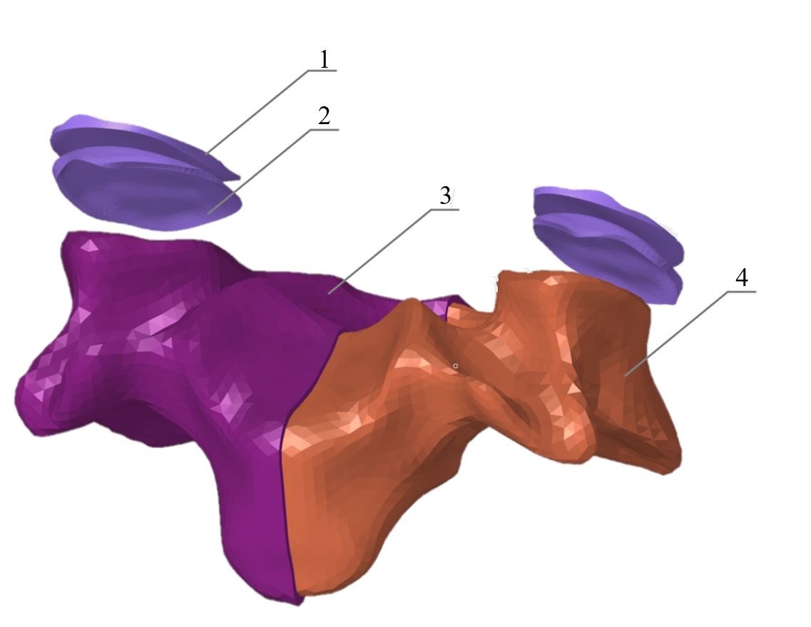
Figure 1. Finite element model of C4.
1 – superior articular surface of the facet joint; 2 – inferior articular surface of the facet joint; 3 – cortical structure; 4 – trabecular structure
The resulting FEM models were imported as orphan mesh into Abaqus CAE software (Simulia, Johnston, Rhode Island, USA) to set the mechanical properties of materials and set boundary conditions for biomechanical analysis of the model. Table 1 presents the values of the mechanical characteristics of some anatomical structures set for all simulated segments.
Table 1. Mechanical characteristics of anatomical structures for all simulated segments
|
Anatomical structure |
Young’s modulus: E (MPa) |
Poisson’s Ratio |
Type of the element |
Published source |
|
Cortical bone |
12000 |
0.3 |
C3D4 |
[30] |
|
Trabecular bone |
100 |
0.2 |
C3D4 |
[30] |
|
Articular cartilage |
10.4 |
0.4 |
C3D4 |
[31] |
|
Cartilaginous endplate |
24 |
0.4 |
C3D8 |
|
A constitutive model of intervertebral disc
IVD in Model 1 is described by linear elastic models of materials presented in Table 2. The geometric configuration of Model 1 is shown in Figure 2.
Table 2. Coefficients of the linear model
|
Segment |
Young’s modulus: E (MPa) |
Poisson’s Ratio |
Type of the element |
|
Lamellae of annulus fibrosus |
8.4 |
0.45 |
C3D4 |
|
Nucleus pulposus |
1 |
0.499 |
C3D4 |

Figure 2. Finite element model of IVD (first configuration).
1 – superior cartilaginous endplate; 2 – NP; 3 – AF; 4 – inferior cartilaginous endplate.
A hyperelastic anisotropic HGO model of the material was used to simulate the anisotropic properties of AF lamellae (Model 2):
 , (1)
, (1)
with
 , (2)
, (2)
where U is strain energy per unit of reference volume; C10 is matrix stiffness coefficient; D is matrix compression ratio; k1, k2 are dimensionless coefficients of material properties providing the nonlinear behavior of collagen fibers; N – number of fiber families (N≤3); Ī1 is the first invariant of the strain deviator; Jel is the modulus of volumetric elasticity; Ēα is engineering strain; Ī4(αα) are pseudoinvariants of the right Cauchy-Green strain tensor and of unit vectors of the fiber direction (per each family). The model assumes that the directions of collagen fibers within each family are dispersed with rotational symmetry relative to a given coordinate system. The parameter K describes the dispersion level of fibers, and its values range from 0 (fibers are aligned without dispersion) to 1/3 (the material becomes isotropic) [22].
In this paper, a simplified formulation of the HGO model is applied without taking into account the coefficient D and with one family of fibers, N:
 , (3)
, (3)
where the left term of the expression describes the mechanical properties of the annulus fibrosus matrix, and the right term describes the distribution and mechanical properties of collagen fibers; the level of fiber dispersion, k=0.113 [28]. Here the left term of the expression describes the mechanical properties of the annulus fibrosus matrix, and the right term describes the distribution and mechanical properties of collagen fibers; the level of fiber dispersion, k=0.113 [28]. The model coefficients for HGO model of annulus fibrosus are presented in Table 3.
Table 3. Coefficients in HGO model of the material for annulus fibrosus
|
Structure |
Model |
C10 MPa |
D |
k1 MPa |
k2 |
k |
Type of the element |
Published source |
|
Lamellae of annulus fibrosus |
Holzapfel-Gasser-Ogden |
0.1 |
0 |
1.8 |
11 |
0.113 |
C3D4H |
[20] |
The nucleus pulposus (Model 2) was modeled as a hyperelastic isotropic material sensu the Mooney-Rivlin model. In this paper, the formulation for incompressible material is used:
 , (4)
, (4)
where C01, C10, D1 are empirically defined constants; Ī1, Ī2 are the first and the second invariants of the left Cauchy-Green strain tensor; J is the determinant of the deformation gradient. For incompressible material, J=1. The model coefficients are presented in Table 4. The geometric configuration of Model 2 is shown in Figure 3.
Table 4. Coefficients in Mooney-Rivlin model of the material for nucleus pulposus
|
Structure |
Model |
C01 MPa |
C10 MPa |
D1 |
Type of the element |
Published source |
|
Nucleus pulposus |
Mooney-Rivlin |
0.12
|
0.03
|
0 |
C3D4H |
[29] |
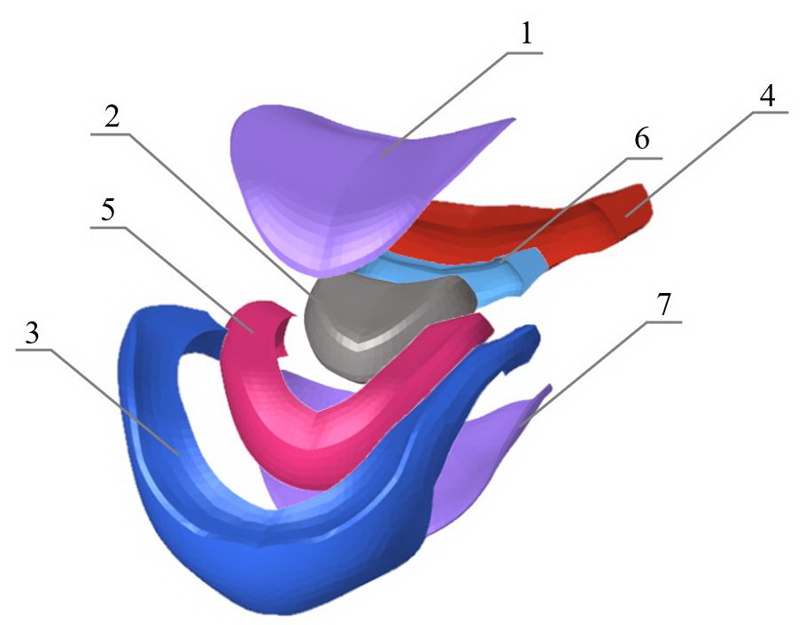
Figure 3. Finite element model of IVD (second configuration).
1 – superior cartilaginous endplate; 2 – NP; 3 – outer anterior AF segment; 4 – outer posterior AF segment; 5 – inner anterior AF segment; 6 – inner posterior AF segment; 7 – inferior cartilaginous endplate.
Model assumptions and boundary conditions
The following assumptions were made about all models: the models do not take into account ligaments, muscles, posture, interaction with the chest. The material of bones, facet joints, endplates is solid, isotropic, linear elastic.
Model 2 was rigidly fixed in the area of the inferior surface of the C5 vertebra body. A concentric force of 800 N was applied to a point in the center of the C3 vertebra body C3 and acts in the direction of the axes of vertebral bodies. This point was kinematically connected to the superior surface of the body of the C3 vertebra. Rigid contact interactions of vertebrae with intervertebral discs were created. The facet joints were linked by a surface-to-surface connection. The properties of the contact interactions of the facet joint were provided by tangential interaction (coefficient of friction = 0.05), along with a normal interaction (soft contact with an exponential increase in pressure between the facets when approaching each other; the value of clearance C=0.2 mm, pressure P=120 MPa). The translamellar cross-bridges were considered in the model by placing a rigid contact between the AF segments; the initial pressure in the nucleus pulposus was 0.19 MPa [4]. The orientation of the collagen fibers was identified for each AF segment sensu [15] in a cylindrical coordinate system (Figure 4). Local reference systems were placed in the geometric centers of the IVD.

Figure 4. Spatial orientation of collagen fibers in IVD.
For the Model 1, same load conditions and contact interactions were set, but without taking into account the collagen fibers of AF lamellae.
Statistical analyses
Statistical data processing and tabulation were performed using Microsoft Excel 2020 for Windows. The correlation analysis of the presented models with experimental data was carried out. To identify the degree of difference between the obtained data sensu experimental and mathematical models, we conducted a comparative analysis via paired samples t-test. The values of parameters with p<0.05 were considered statistically significant.
Results
Load-displacement curves were obtained for two models (Figure 5). Displacement values were measured in the geometric center of the C4 vertebra. Maximum displacement value for the isotropic model was 1.15 mm, whereas mean was 0.73±0.45 mm. For anisotropic model, maximum and mean displacement values were 0.86 mm and 0.47±0.24 mm, respectively.
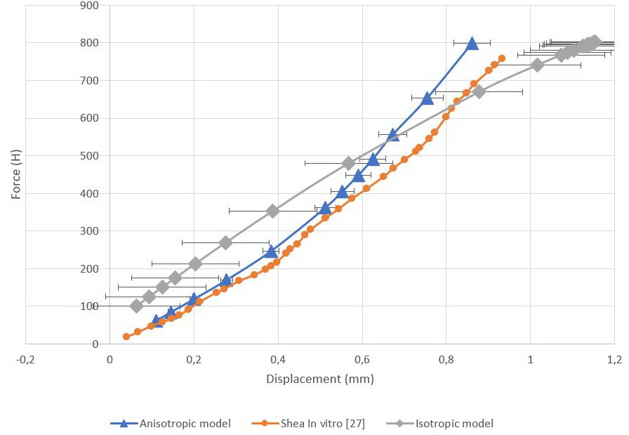
Figure 5. Load-displacement curves.
Orange curve represents in vitro values, gray curve represents isotropic model, blue curve represents anisotropic model.
We employed paired samples t-test of means for the obtained data. The values are presented in Tables 5 (isotropic model) and 6 (anisotropic model).
Table 5. Results of the t-test for isotropic model
|
Descriptive statistics |
Shea in vitro [27] |
Isotropic model |
|
Mean |
0.52 |
0.73 |
|
Variance |
0.07 |
0.17 |
|
Observations |
12 |
12 |
|
Pearson correlation |
0.96 |
|
|
Hypothetical difference of means |
0 |
|
|
df |
11 |
|
|
t-statistic |
-4.27 |
|
|
P(T≤t) one-sided |
0.00065 |
|
|
t critical one-sided |
1.79 |
|
|
P(T≤t) two-sided |
0.001 |
|
|
t critical two-sided |
2.20 |
|
Table 6. Results of the t-test for anisotropic model
|
Descriptive statistics |
Shea in vitro [27] |
Anisotropic model |
|
Mean |
0.52 |
0.47 |
|
Variance |
0.07 |
0.06 |
|
Observations |
12 |
12 |
|
Pearson correlation |
0.99 |
|
|
Hypothetical difference of means |
0 |
|
|
df |
11 |
|
|
t-statistic |
6.02 |
|
|
P(T<=t) one-sided |
4.30e-05 |
|
|
t critical one-sided |
1.79 |
|
|
P(T<=t) two-sided |
8.60e-05 |
|
|
t critical two-sided |
2.20 |
|
The stress profile obtained for two IVDs in the isotropic model was measured in the median plane of the IVD and then normalized. Figures 6 and 7 illustrate von Mises stress profiles. For the C3C4 IVD, tension peaks occurred on the AF anterior part during the entire load cycle. Hence, with a concentric force of 215 N, the maximum tension value in the C3C4 IVD was estimated at 1.26 MPa, and 4.64 MPa with a concentric force of 800 N. The tensions in the C4C5 IVD were concentrated as a mirror reflection, in the back of the disc. The maximum tension value at 215 N was 1.23 MPa, while at 800 N, it was 4.95 MPa.
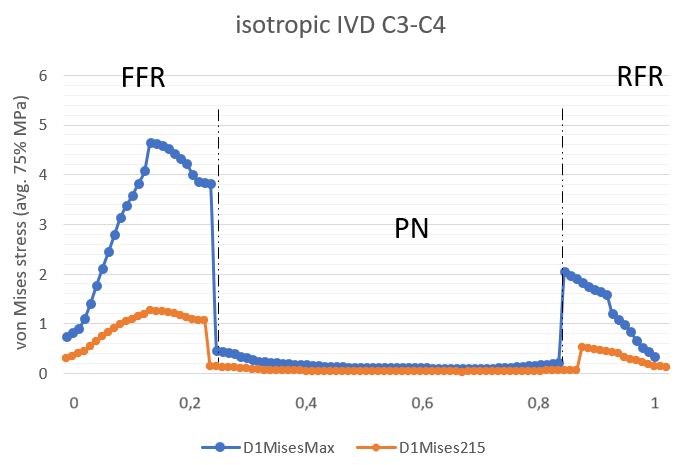
Figure 6. Stress profile sensu von Mises in C3C4 IVD (isotropic model).
AAF is an anterior part of the AF, PAF is the posterior part of the AF. Blue curve depicts IVD given the load of 800N, orange curve describes IVD given the load of 215N.
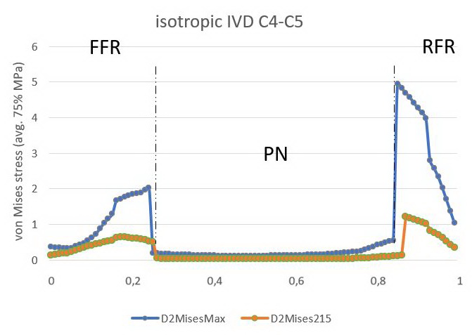
Figure 7. Stress profile sensu von Mises in C4C5 IVD (isotropic model)
AAF is an anterior part of the AF, PAF is the posterior part of the AF. Blue curve depicts IVD given the load of 800N, orange curve describes IVD given the load of 215N.
Stress plots for the C3-C5 segment with an isotropic IVD model are shown in Figure 8. The maximum value of the von Mises stress was concentrated at the boundary of the C4 vertebra body and C3C4 IVD AF (7.923 MPa).

Figure 8. Stress diagram sensu von Mises of the studied spine segment, C3-C5 (IVD isotropic model).
The von Mises stress diagrams and contact stress diagrams were constructed for facet joints (Figure 9).

Figure 9. The von Mises stress diagram for superior articular surface of the facet joint (1) and contact stress diagram for its inferior articular surface (isotropic linear model).
The anisotropic model stress profile was measured in the median planes of the IVD and then normalized. Stress peaks during the entire stress cycle occurred at the boundaries of the external and internal anterior AF. The maximum value for C3C4 IVD was 5.75 MPa (Figure 10); and for C4C5 IVD, it was 3.43 MPa (Figure 11). The minimum was concentrated in the NP in two discs.
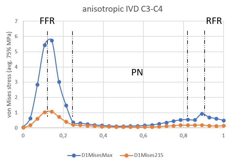
Figure 10. Stress profile sensu von Mises in C3C4 IVD (anisotropic model).
AAF is an anterior part of the AF, PAF is the posterior part of the AF.
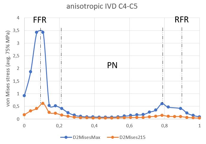
Figure 11. Stress profile sensu von Mises in C4C5 IVD (anisotropic model).
AAF is an anterior part of the AF, PAF is the posterior part of the AF.
Discussion
We carried out the stress-strain state analysis of two IVD configurations via FEM. Model 1 included AF, NP, cartilaginous endplates, and was described by an isotropic linear model of the material. Model 2 encompassed four AF segments (internal and external, which in turn were divided into anterior and posterior), NP, cartilaginous endplates. AF was described by an anisotropic hyperelastic HGO model. NP was described by the isotropic hyperelastic Mooney-Rivlin model. The results of computer simulations were compared with in vitro experimental data for C3-C5 segments [27].
Predicted displacements for both models correlated well with experimental data [27]. However, stress profiles in the segment with an isotropic IVD model were fundamentally different from the segment with an anisotropic model. The load in the isotropic C3C4 IVD was concentrated in the anterior part of the AF, whereas in C4C5 IVD it displaced to the posterior part of the AF. Such mirror distribution of the load could be related to the IVD material model. Regarding the stress profile of the anisotropic model, it could be seen that the axial load in the AF decreased posteriorly, where the orientation of the collagen fibers had maximum value relative to the horizontal plane. Such morphological organization could be necessary for better control of the axial load in the posterior part of the IVD, but was making the posterior AF part more sensitive to tangential loads originating from the NP. In displacement diagrams for the anisotropic model, global displacement maxima were observed in the posterior wall of the C3C4 IVD. The values of S22 in this disc were maximum in the posterior part of the AF.
The linear behavior of the isotropic model could be seen on the load-displacement curve. Despite this, there was a nonlinearity in the curve associated with setting boundary conditions for facet joints. The pressure between the articular plates was increasing exponentially when the clearance value of 0.2 mm was achieved. The nature of this nonlinearity enabled us to assume that poor prediction of the components of displacements on the in vitro curve [27] was associated with the mechanical properties of facet joints.
The anisotropic HGO model allowed simulating various configurations of the IVD extracellular matrix. The degree of degeneration could be expressed by means of the dispersion level of the fibers, K: the greater was the dispersion value, the higher was the degree of degeneration. However, for predictive models, the geometry of the patient musculoskeletal system remained an important factor [8]. Despite these findings, we postulate that anisotropic IVD models with the proposed geometric configuration describes the biomechanics of C3-C5 cervical spine segment in the norm quite well. This configuration made it possible to take into account the nonlinearity and local anisotropy of AF at a relatively low computational effort. The calculation of the model on a workstation with a 10-core processor (Intel Core i9 10900KF) took 6,220.8 seconds of CPU time, when the calculation of the isotropic model took 9,838 seconds of CPU time.
Conclusion
The proposed geometric and constitutive configurations of the IVD take into account specific morphological features at low computational costs, thereby facilitating the modeling of degenerative disc changes. The proposed approach expands prospects for analyzing the pathogenesis of dorsopathies, preoperative planning of surgical interventions on IVD, along with the development of therapeutic and preventive measures for patients with such pathology.
Limitations
A significant limitation of the model is its inability of modeling IVD with hernia and protrusion without routine preparation of the model geometry. The model requires extended validation in terms of torsion, flexion and extension.
Conflict of interest
The authors declare no apparent or potential conflicts of interest associated with the publication of this article.
Ethical approval
All procedures performed in studies involving human participants were in compliance with the ethical standards of the institutional research committee and with 1964 Declaration of Helsinki and its later amendments, or comparable ethical standards.
- Popelyansky YaYu. Orthopedic Neurology (Vertebroneurology). 3rd Ed. Moscow, Russia: MEDpress-inform. 2003; 670 p. Russian. https://www.elibrary.ru/item.asp?id=19520568.
- Health in the European Union. Report. Special Eurobarometer 2007; 125 p. https://ec.europa.eu/health/ph_publication/eb_health_en.pdf.
- Zhang Z, Li Y, Liao Z, Liu W. Research progress and prospect of applications of finite element method in lumbar spine biomechanics. Sheng Wu Yi Xue Gong Cheng Xue Za Zhi 2016; 33(6): 1196-1202. Chinese. https://pubmed.ncbi.nlm.nih.gov/29715419.
- Khoroshev DV, Ilyalov OR, Ustyuzhantsev NE, Nyashin YI. Biomechanical modeling of the intervertebral disc of the human lumbar spine – The problem current state. Russian Journal of Biomechanics 2019; 23(3): 411-422. Russian. https://www.elibrary.ru/item.asp?id=42638877.
- Zakharov AV, Okushko VR, Vturin SA, Moseychuk VV, Petrov AA, Suetenkov DE. Demonstration of skull bones mobility using optical methods: Practical importance in medicine. In: Proc. SPIE 9031, Saratov Fall Meeting 2013: Optical Technologies in Biophysics and Medicine XV; and Laser Physics and Photonics XV. 2014: 903106. https://doi.org/10.1117/12.2051266.
- Martin D. Dynamic reconstruction of the spine. Acta Chir Belg 2016; 116(1): 69. https://doi.org/10.1080/00015458.2016.1147744.
- Bublik LA, Likholetov AN. Experimental biomechanical rationale for transpedicular spondylosyndesis with vertebroplasty based on a study of finite element model of the vertebral column fragment. Trauma 2014; 15(1): 66-73. https://www.elibrary.ru/item.asp?id=21460041.
- Henninger HB, Reese SP, Anderson AE, Weiss JA. Validation of computational models in biomechanics. Proc Inst Mech Eng H 2010; 224(7): 801-812. https://doi.org/10.1243/09544119jeim649.
- Liang D, Tu GJ, Han YX, Guo DW. Accurate simulation of the herniated cervical intervertebral disc using controllable expansion: A finite element study. Comput Methods Biomech Biomed Engin 2021; 24(8): 897-904. https://doi.org/10.1080/10255842.2020.1857745.
- Östh J, Brolin K, Svensson MY, Linder A. A female ligamentous cervical spine finite element model validated for physiological loads. J Biomech Eng 2016; 138(6): 061005. https://doi.org/10.1115/1.4032966.
- Nikkhoo M, Cheng CH, Wang JL, Khoz Z, El-Rich M, Hebela N, et al. Development and validation of a geometrically personalized finite element model of the lower ligamentous cervical spine for clinical applications. Comput Biol Med 2019; 109: 22-32. https://doi.org/10.1016/j.compbiomed.2019.04.010.
- Sun MS, Cai XY, Liu Q, Du CF, Mo ZJ. Application of simulation methods in cervical spine dynamics. J Healthc Eng 2020; 2020: 7289648. https://doi.org/10.1155/2020/7289648.
- Kumaresan S, Yoganandan N, Pintar FA, Maiman DJ. Finite element modeling of the cervical spine: Role of intervertebral disc under axial and eccentric loads. Med Eng Phys 1999; 21(10): 689-700. https://doi.org/10.1016/s1350-4533(00)00002-3.
- Kumaresan S, Yoganandan N, Pintar FA. Finite element analysis of the cervical spine: A material property sensitivity study. Clin Biomech (Bristol, Avon) 1999; 14(1): 41-53. https://doi.org/10.1016/s0268-0033(98)00036-9.
- Holzapfel GA, Schulze-Bauer CA, Feigl G, Regitnig P. Single lamellar mechanics of the human lumbar anulus fibrosus. Biomech Model Mechanobiol 2005; 3(3): 125-140. https://doi.org/10.1007/s10237-004-0053-8.
- Han SK, Chen CW, Wierwille J, Chen Y, Hsieh AH. Three-dimensional mesoscale analysis of translamellar cross-bridge morphologies in the annulus fibrosus using optical coherence tomography. J Orthop Res 2015; 33(3): 304-311. https://doi.org/10.1002/jor.22778.
- Schollum ML, Robertson PA, Broom ND. A microstructural investigation of intervertebral disc lamellar connectivity: Detailed analysis of the translamellar bridges. J Anat 2009; 214(6): 805-816. https://doi.org/10.1111/j.1469-7580.2009.01076.x.
- Disney CM, Eckersley A, McConnell JC, Geng H, Bodey AJ, Hoyland JA, et al. Synchrotron tomography of intervertebral disc deformation quantified by digital volume correlation reveals microstructural influence on strain patterns. Acta Biomater 2019; 92: 290-304. https://doi.org/10.1016/j.actbio.2019.05.021.
- Monteiro NMB, da Silva MPT, Folgado JOMG, Melancia JPL. Structural analysis of the intervertebral discs adjacent to an interbody fusion using multibody dynamics and finite element co-simulation. Multibody Syst Dyn 2011; 25: 245-270. https://doi.org/10.1007/s11044-010-9226-7.
- Momeni Shahraki N, Fatemi A, Goel VK, Agarwal A. On the use of biaxial properties in modeling annulus as a Holzapfel-Gasser-Ogden material. Front Bioeng Biotechnol 2015; 3: 69. https://doi.org/10.3389/fbioe.2015.00069.
- O’Connell GD, Sen S, Elliott DM. Human annulus fibrosus material properties from biaxial testing and constitutive modeling are altered with degeneration. Biomech Model Mechanobiol 2012; 11(3-4):493-503. https://doi.org/10.1007/s10237-011-0328-9.
- Holzapfel GA, Gasser TC, Ogden RW. A new constitutive framework for arterial wall mechanics and a comparative study of material models. J Elasticity 2000; 61(1): 1-48. https://doi.org/10.1023/A:1010835316564.
- Eberlein R, Holzapfel GA, Schulze-Bauer CAJ. An anisotropic model for annulus tissue and enhanced finite element analyses of intact lumbar disc bodies. Computer Methods in Biomechanics and Biomedical Engineering 2001; 4(3): 209-229, https://doi.org/10.1080/10255840108908005.
- Tavakoli J, Diwan AD, Tipper JL. Elastic fibers: The missing key to improve engineering concepts for reconstruction of the nucleus pulposus in the intervertebral disc. Acta Biomater 2020; 113: 407-416. https://doi.org/10.1016/j.actbio.2020.06.008.
- Barthelemy VM, van Rijsbergen MM, Wilson W, Huyghe JM, van Rietbergen B, Ito K. A computational spinal motion segment model incorporating a matrix composition-based model of the intervertebral disc. J Mech Behav Biomed Mater 2016; 54: 194-204. https://doi.org/10.1016/j.jmbbm.2015.09.028.
- Li S, Patwardhan AG, Amirouche FM, Havey R, Meade KP. Limitations of the standard linear solid model of intervertebral discs subject to prolonged loading and low-frequency vibration in axial compression. J Biomech 1995; 28(7): 779-790. https://doi.org/10.1016/0021-9290(94)00140-y.
- Shea M, Edwards WT, White AA, Hayes WC. Variations of stiffness and strength along the human cervical spine. J Biomech 1991; 24(2): 95-107. https://doi.org/10.1016/0021-9290(91)90354-p.
- Mosbah MS, Bendoukha M. Anisotropic response of the Holzapfel’s constitutive model for the lumbar spine considering degenerative conditions. Journal of Silicate Based and Composite Materials 2018; 70(4): 110-114. https://doi.org/10.14382/epitoanyag-jsbcm.2018.20.
- Cai XY, Sun MS, Huang YP, Liu ZX, Liu CJ, Du CF, et al. Biomechanical effect of L4 -L5 intervertebral disc degeneration on the lower lumbar spine: A finite element study. Orthop Surg 2020; 12(3): 917-930. https://doi.org/10.1111/os.12703.
- Agarwal A, Agarwal AK, Goel VK. The endplate morphology changes with change in biomechanical environment following discectomy. Int J of Clinical Medicine 2013; 4(7A): 8-17. http://dx.doi.org/10.4236/ijcm.2013.47A1002.
- Mengoni M. Biomechanical modelling of the facet joints: A review of methods and validation processes in finite element analysis. Biomech Model Mechanobiol 2021; 20(2): 389-401. https://doi.org/10.1007/s10237-020-01403-7.
Received 20 April 2021, Revised 15 November 2021, Accepted 3 February 2022
© 2021, Russian Open Medical Journal
Correspondence to Artur L. Ovsepyan. E-mail: aqturovsepyan@gmail.com.